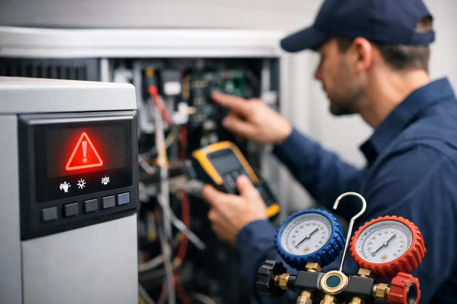
A flashing LED, a code on a communicating thermostat, or a message in a manufacturer app can change the direction of a service call in seconds. HVAC error codes are useful because they point a technician toward a failed safety, missing input, communication problem, or operating condition. They do not replace the diagnostic process. The code is a starting point. The measurements, sequence of operation, and equipment history determine the repair.
For a technician in the field, the goal is not to memorize every code across every brand. The goal is to find the correct information quickly, understand what the control board is reporting, and verify the actual cause before replacing a part. That approach reduces callbacks, protects the customer from unnecessary repairs, and helps the next technician understand what happened.
What HVAC Error Codes Actually Tell You
An error code is the control's report of a condition it detected. Depending on the equipment, it may identify an open pressure switch, a failed flame-proving cycle, high-limit trip, condensate safety issue, sensor fault, low-voltage problem, inverter communication failure, or another abnormal condition.
That distinction matters. A pressure-switch code does not automatically mean the pressure switch failed. The switch may be open because the inducer is not creating enough negative pressure, the vent is restricted, the drain is backed up, tubing is damaged, or the board is not supplying the correct signal. Replacing the switch without testing the circuit may get heat running temporarily, but it may leave the real failure in place.
The same rule applies to nearly every code. Treat the code as a symptom reported by the control, not a parts list.
Start With the Exact Equipment Information
Codes are manufacturer-specific, and they can vary by model, board revision, and equipment generation. A two-flash fault on one furnace may have an entirely different meaning on another. Before interpreting a code, confirm the manufacturer, model number, serial number, and control board part number when available.
Also identify where the code is displayed. It may come from the furnace control board, outdoor unit board, thermostat, zone panel, economizer controller, or variable-speed drive. In communicating systems, one component can display a fault generated by another component. A thermostat message may be accurate, but the source of the problem may be outside at the condenser or inside at the air handler.
If the unit has a fault-history function, check it before cycling power. Intermittent faults often disappear when power is reset, and the stored history can provide useful context. Record active codes, historical codes, flash patterns, and any accompanying status lights.
A Field Process for Reading HVAC Error Codes
A repeatable process keeps the call organized when the equipment is noisy, access is tight, or the customer is waiting for an answer. Start with the code, then work outward through the system.
Confirm the complaint and operating mode
Ask what the customer noticed and when it began. No cooling after a storm is a different starting point than a furnace that only fails during the coldest part of the night. Verify the thermostat call, setpoint, indoor temperature, outdoor conditions, and whether the system is attempting to start.
Then observe the sequence of operation. On a gas furnace, for example, watch for the call for heat, inducer start, pressure-switch closure, ignition, flame proving, blower delay, and stable operation. A code may tell you the sequence stopped, but watching the sequence tells you when and how it stopped.
Use the manual for that exact unit
A generic code chart can be helpful for orientation, but it should not be the final authority. Use the installation, service, or control-board documentation tied to the specific equipment. Look for the code definition, reset behavior, expected readings, wiring diagram, and troubleshooting notes.
This is where access to organized manuals and guided diagnostic information saves real time. Searching through a large PDF on a phone while standing at a rooftop unit is not an efficient diagnostic system. A field-ready reference should make the relevant information available when the technician needs it.
Test the condition behind the code
Once the code identifies the circuit or operating condition, test it. Check voltage, continuity, resistance, pressure, temperature, airflow, static pressure, refrigerant conditions, drainage, and communication signals as the equipment requires. Use the wiring diagram to verify where power and signals should be present.
Avoid testing only one component in isolation. A limit switch that is open may be doing its job because of restricted airflow. A low-pressure condition may be tied to airflow, refrigerant charge, a metering issue, or a control problem. A communication code may come from damaged wiring, incorrect polarity, poor connections, electrical noise, or a failed board.
The fastest repair is often the one that takes an extra few minutes to prove.
Common Code Categories and What to Check
Many fault codes fall into a few practical categories. Knowing the category helps technicians build a logical test plan rather than jumping from part to part.
Safety and limit faults
High limits, rollout switches, pressure switches, freeze protection, float switches, and condensate safeties exist to stop equipment before damage or unsafe operation occurs. Do not bypass a safety to get the system running. Identify why it opened.
For airflow-related limit faults, inspect filters, return and supply restrictions, blower operation, wheel cleanliness, motor speed settings, coil condition, and duct static pressure. For combustion-related safeties, inspect venting, intake air, condensate drainage, inducer performance, heat exchanger conditions, and proper combustion setup.
Ignition and flame-proving faults
A furnace that lights and then shuts down may report a flame-sense fault. The flame sensor could be contaminated, but the issue can also involve poor grounding, weak flame carryover, gas-pressure problems, burner condition, polarity, or a failing control board. Clean the sensor if needed, but verify flame-sense microamps and the complete ignition sequence.
If ignition never occurs, determine whether the board is sending the correct output and whether all permissives have been satisfied. The igniter, gas valve, pressure switch circuit, and board outputs should be tested in sequence.
Sensor and temperature faults
Thermistors, discharge sensors, coil sensors, and supply-air sensors can fail open, fail shorted, drift out of range, or report an actual temperature problem. Compare the sensor's resistance or voltage to the manufacturer's temperature chart. Then compare that value with the actual measured temperature.
A sensor code can be caused by a damaged sensor, but it can also expose poor airflow, a dirty coil, refrigerant problems, or an installation issue. The sensor may be the messenger, not the failure.
Communication and low-voltage faults
Modern systems depend on clean low-voltage power and reliable communication. Check transformer output, fuse condition, common connections, polarity, terminal tightness, wire damage, moisture, and proper addressing or configuration. Disconnecting and reconnecting communication wiring without documenting terminal locations can create a second problem, especially on multi-component systems.
When troubleshooting intermittent communication faults, inspect for loose splices, rubbed wire, water intrusion, and voltage drop under load. A system can communicate normally while idle and fail only when contactors, motors, or other loads energize.
Document the Fix So the Next Call Starts Ahead
A code without context is limited. A good service note records the original complaint, exact code, operating conditions, test results, root cause, repair completed, and final verification. This information is valuable for recurring issues, warranty decisions, training, and customer communication.
For teams, shared diagnostic notes can prevent the same problem from being solved from scratch by three different technicians. HVAC Assist Pro is built around that practical need: keep manuals, guided problem solving, calculators, and technician-shared field knowledge available in one account-based workspace. It is not business management software. It is support for making better diagnostic decisions at the equipment.
Photos can also help when used with purpose. Capture the model and serial data, board flash pattern, wiring condition, failed component, meter reading, and completed repair when those details will support the record. A clear note and a few useful photos are more valuable than a long, vague description.
When a Code Needs a Slower Approach
Some faults should not be rushed. Repeated rollout trips, suspected heat exchanger problems, high-voltage electrical damage, refrigerant leaks, combustion concerns, and inverter-drive failures require careful testing and manufacturer procedures. Resetting the equipment repeatedly may erase evidence or create additional risk.
If a fault returns after a verified repair, step back and review the entire operating condition. Look for changes in static pressure, venting, electrical supply, refrigerant circuit behavior, control configuration, or recent work performed on the system. Repeat failures usually mean the first repair addressed a result rather than the source.
The best use of HVAC error codes is simple: let the equipment tell you where to look, then let your testing tell you what to fix. Build that habit on every call, and the code becomes less of a roadblock and more of a useful direction.