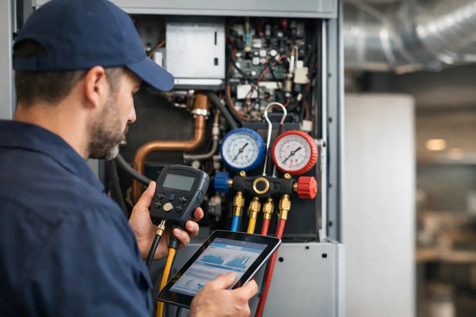
A no-cool call is rarely solved by asking, “What part failed?” The better first question is, “What is this system trying to do, and where did the process stop?” That is the practical answer to how to work an HVAC system in the field. A technician who understands the operating sequence can test with purpose instead of replacing parts by guesswork.
An HVAC system is a connected process. Air must move. Refrigerant must absorb and reject heat. Electrical components must energize in the correct order. Controls must receive the right inputs and make the right decisions. A fault in any one area can look like a problem somewhere else, which is why a consistent diagnostic method matters.
How to Work an HVAC System by Following the Sequence
Start by separating the system into four working sections: airflow, refrigeration, electrical power, and controls. This prevents a technician from jumping straight to gauges or a meter before confirming basic conditions.
For a typical split air-conditioning system, the thermostat calls for cooling. The indoor blower and outdoor unit are commanded to operate. The compressor circulates refrigerant, the indoor coil absorbs heat from the air moving across it, and the outdoor coil rejects that heat outside. The blower then delivers cooler air through the duct system.
A heat pump uses the same basic refrigeration process, but a reversing valve changes the direction of refrigerant flow during heating. That detail changes what the indoor and outdoor coils do, but it does not change the need for a disciplined sequence of checks.
Before testing, confirm the complaint. Is the system not starting, running but not cooling, freezing, short cycling, tripping a breaker, or delivering uneven comfort? Ask what changed, when the issue began, and whether the equipment has been serviced recently. A clear complaint narrows the diagnostic path before you remove a panel.
Then verify the obvious operating conditions. Confirm thermostat mode and setpoint, disconnects and breakers, filter condition, supply and return registers, and visible equipment condition. These are not shortcuts. They are part of problem solving. A clogged filter, closed return, incorrect thermostat setting, or open disconnect can imitate a much larger failure.
Start With Airflow Before Chasing Refrigerant
Airflow is often the first system function to evaluate because poor airflow changes nearly every reading that follows. Low airflow across an evaporator can lower suction pressure, cause coil icing, reduce capacity, and make a technician suspect a refrigerant issue. High static pressure can point to a restrictive filter, undersized ductwork, a dirty coil, a failed blower adjustment, or closed dampers.
Check the filter, blower wheel, evaporator coil, return path, and supply path. Verify that the blower is running at the appropriate speed for the mode and equipment setup. On variable-speed systems, do not assume the motor is at fault simply because airflow feels weak. The control may be limiting output because of a safety condition, incorrect configuration, or an external static-pressure issue.
Temperature split can be useful, but it is not a stand-alone diagnosis. It depends on indoor load, humidity, airflow, and outdoor conditions. A technician should treat it as one piece of evidence, not a final answer.
If the coil is frozen, do not rush to add refrigerant. Shut down cooling as needed, allow the coil to thaw, and find the reason for the freeze-up. Common causes include restricted airflow, low refrigerant charge, a metering device issue, or blower operation problems. Readings taken on an iced coil can send the diagnosis in the wrong direction.
Understand the Refrigeration Circuit in Real Terms
The refrigeration circuit moves heat. The compressor raises refrigerant pressure and temperature. At the outdoor coil in cooling mode, the refrigerant rejects heat and condenses into a high-pressure liquid. The metering device drops its pressure. At the indoor coil, refrigerant evaporates and absorbs heat from the air.
That sequence gives purpose to pressure, temperature, superheat, and subcooling readings. Gauges alone do not diagnose a system. A pressure number has meaning only when it is paired with refrigerant type, outdoor temperature, indoor load, airflow, and system design.
Use measured line temperatures and saturation temperatures to calculate superheat and subcooling. Compare the results with the equipment’s charging method and manufacturer specifications. A fixed-orifice system and a TXV system are not evaluated exactly the same way. Nor should a technician apply one target number to every unit, every day, and every load condition.
Look for patterns instead of isolated readings. Low suction with low superheat may suggest an airflow restriction or a metering issue, depending on the rest of the system data. Low suction with high superheat may indicate a starved evaporator, but the cause could be low charge, restriction, or a feed problem. High head pressure may result from a dirty condenser, poor condenser airflow, overcharge, noncondensables, or high outdoor ambient conditions.
The trade-off is time versus certainty. Skipping airflow and electrical checks may get gauges connected faster, but it often creates a longer call. A complete set of conditions produces a better decision and a more defensible repair.
Test Electrical Power and Components Under Load
Electrical diagnosis should follow the circuit from source to load. Confirm incoming voltage at the disconnect or panel, then verify voltage at the contactor, compressor, fan motor, transformer, control board, and other components involved in the call. A component can have voltage present but still fail under load because of a weak connection, damaged wire, failing contactor, or voltage drop.
Inspect contactor points, terminals, capacitors, fuses, wiring, and grounds. Check amp draw against rated values when conditions allow. A compressor drawing locked-rotor amperage, a condenser fan drawing excessive amperage, or a blower motor that cannot maintain speed gives useful direction. But nameplate data is a reference, not permission to ignore the rest of the circuit.
Capacitors deserve careful testing. A capacitor that appears normal can still be outside its rated tolerance. A replacement must match the required microfarad rating and meet the appropriate voltage rating. More importantly, find out why it failed. Heat, weak motor windings, poor airflow around the equipment, and repeated electrical stress can shorten capacitor life.
Always use lockout and tagout practices where applicable, verify the circuit is de-energized before handling components, and follow equipment-specific safety procedures. Diagnosis is only useful when the technician leaves the job safely.
Follow Controls From the Thermostat to the Safety Circuit
Controls are the decision-makers of the system. Begin with the thermostat call, then trace the low-voltage circuit through the transformer, board, relays, pressure switches, float switches, limit switches, and safeties. Determine where the signal begins and where it stops.
For example, if the thermostat is calling but the outdoor contactor is not pulling in, confirm 24 volts at the contactor coil. If voltage is missing, work backward through the safety circuit and board output. If correct voltage is present but the contactor will not close, the contactor or coil may be defective. This is more efficient than replacing a thermostat because the system “will not turn on.”
Modern communicating equipment adds another layer. Error codes, sensor values, and board LEDs are useful, but they should be verified with actual measurements. A code identifies a condition the control recognizes. It does not always identify the root cause.
Record What You Found So the Next Call Starts Ahead
Good field notes protect time and preserve knowledge. Record the customer complaint, operating conditions, measured voltages, pressures, temperatures, amperage, error codes, repairs made, and final performance checks. Clear notes help the next technician understand what happened without searching through texts, old manuals, or memory.
For teams, a shared diagnostic workspace can turn one technician’s solved problem into a repeatable field resource. HVAC Assist Pro is built around that practical need: keeping manuals, guided diagnostic information, calculators, and technician discussion available when the equipment is in front of you.
The goal is not to memorize every fault on every model. The goal is to build a repeatable way to think: verify the complaint, follow the operating sequence, measure the system, and let the evidence point to the repair. On the next difficult call, slow down long enough to identify where the process breaks. That habit saves more time than any shortcut.