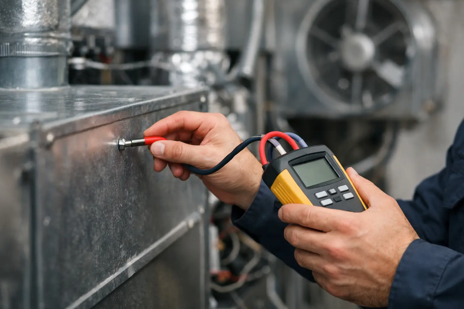
A blower can sound normal, move some air, and still be working against excessive resistance. That is why technicians calculate HVAC static pressure instead of judging airflow by feel at a register. A few accurate manometer readings can point to a plugged filter, restrictive coil, undersized return, closed damper, or a duct system that cannot support the equipment’s required airflow.
Static pressure testing is not a substitute for checking temperature split, refrigerant performance, or electrical operation. It gives you a different piece of the diagnostic picture: how hard the blower must work to move air through the external duct system. Used with the manufacturer’s blower data, it turns a vague airflow complaint into a measurable problem.
What HVAC Static Pressure Actually Measures
Static pressure is the resistance to airflow in a duct system. It is commonly measured in inches of water column, written as in. w.c. The more restrictive the path, the higher the pressure the blower must overcome.
For most residential and light commercial forced-air equipment, technicians focus on total external static pressure, or TESP. “External” means the pressure drop across the components outside the equipment cabinet that affect airflow: return ductwork, filters, supply ductwork, coils, grilles, dampers, and accessories. The manufacturer’s rated maximum external static pressure is the number that matters, not a generic target pulled from memory.
A common rating is 0.50 in. w.c., but that does not make 0.50 correct for every system. Some air handlers, furnaces, communicating systems, and higher-static applications have different limits. Always check the unit’s installation instructions, blower performance chart, or data plate information before calling a reading acceptable.
Tools and Test Locations
You need a calibrated digital manometer, static pressure tips, tubing, a drill, approved plugs or tape for test holes, and the equipment’s blower performance data. A standard pitot tube is not the preferred tool for static pressure testing in this application. Static tips are designed to sense pressure without facing directly into the moving airstream.
To measure TESP, take one reading on the return side of the blower and one on the supply side. The return reading is normally negative because the blower is pulling air. The supply reading is normally positive because the blower is pushing air.
The exact test locations depend on the equipment configuration. On a typical furnace with an evaporator coil above it, place the return test port between the filter and the blower compartment, and place the supply test port after the coil. This captures the resistance of the filter, coil, and duct system.
Do not place the supply probe between the furnace heat exchanger and the evaporator coil when your goal is total external static pressure. That location leaves the coil out of the reading, which can hide one of the most common restrictions in cooling mode. On an air handler, follow the same principle: test on each side of the blower while including the external components called for by the manufacturer’s procedure.
Keep test ports away from turbulent areas when possible. Avoid elbows, transitions, takeoffs, and coil faces. A straight section of duct is preferred. If there is no ideal location, document where you tested and use consistent locations when comparing readings later.
How to Calculate HVAC Static Pressure
Set the thermostat so the indoor blower operates at the airflow setting you need to evaluate. For a cooling complaint, test in cooling mode after the system has stabilized. For a heating complaint, test in heating mode if that is the airflow setting in question. A variable-speed blower may run at very different speeds in continuous fan, heating, cooling, dehumidification, and staging modes.
With the manometer zeroed, connect the negative port to the return-side static tip. Record the reading. For example, the return static pressure may be -0.28 in. w.c. Then measure the supply side with the positive port. Assume the supply static pressure is +0.42 in. w.c.
Use the absolute values of both readings and add them:
TESP = return static pressure + supply static pressure
Because return pressure is negative, the field calculation is usually written this way:
TESP = |-0.28| + |+0.42| = 0.70 in. w.c.
The system in this example has 0.70 in. w.c. total external static pressure. If the manufacturer’s maximum rated TESP is 0.50 in. w.c., the system is over the rated resistance by 0.20 in. w.c. That does not identify the failed part by itself. It tells you to find where the pressure is being lost.
Record the operating conditions with every test: filter condition and size, blower speed or airflow command, heating or cooling mode, stages operating, accessory positions, and whether doors and panels were installed. These details prevent misleading comparisons between visits.
Use the Blower Chart After the Calculation
TESP is only half of the airflow diagnosis. Find the equipment’s blower performance table and match the measured external static pressure to the active blower speed, tap, or programmed setting. The chart estimates the airflow the blower can deliver at that resistance.
For example, a blower set for nominal 1,200 CFM may only deliver 900 CFM at a higher-than-expected static pressure. That reduced airflow can contribute to coil freezing, low sensible capacity, nuisance limits, high temperature rise, increased blower watt draw, and comfort complaints. The chart also shows why increasing blower speed is not always a complete repair. It can restore some airflow, but it may increase noise, electrical use, and stress on an already restrictive duct system.
Find the Restriction With Pressure Drop Tests
Once TESP is high, measure individual pressure drops. This is where the test becomes practical problem solving rather than a single pass-fail number.
Measure before and after the filter to find filter pressure drop. A dirty filter may be restrictive, but so can an overly dense filter, a filter rack that is too small, or a return grille that cannot provide enough face area. Measure before and after the evaporator coil to identify coil pressure drop. A dirty coil, a matted coil surface, or an improperly selected coil can add significant resistance.
If the filter and coil drops are reasonable, the remaining restriction is likely in the return or supply duct system. Compare return and supply static readings. A heavily negative return reading often points toward return-side restrictions such as undersized duct, blocked return paths, restrictive grilles, or a collapsed flex duct. A high supply reading can indicate undersized supply trunks, closed dampers, crushed flex, restrictive registers, or zoning issues.
Do not diagnose from one side alone. A return static pressure of -0.45 in. w.c. may be a clear warning, but the supply reading, equipment rating, blower setting, and system layout still matter. Duct systems often have restrictions on both sides.
Field Errors That Produce Bad Numbers
Static pressure is simple to calculate, but poor setup creates poor data. Common errors include testing with the blower door removed, reading in the wrong operating mode, using the wrong test location, failing to zero the manometer, or leaving a tubing connection loose.
Another frequent mistake is measuring a clean filter and assuming the homeowner’s typical filter will perform the same way. If the customer uses a higher-MERV filter, test with the filter that normally operates in the system. Also verify that all supply registers, return grilles, and zone dampers are in their normal positions. A test with several registers closed may reveal a real problem, but it does not represent normal system operation unless that is how the system is routinely used.
After testing, seal every test port. Unsealed holes can whistle, leak air, or become a source of customer concern. Note the readings on the service invoice or in the job record so the next technician has a baseline.
Use Static Pressure to Support the Repair
A high static pressure reading is evidence, not a sales pitch. Explain what the numbers mean in plain terms: the blower is operating above its designed resistance, and the measured drops show where the restriction is located. Then present the repair that addresses that restriction, whether it is coil cleaning, filter-rack correction, return improvement, duct repair, damper adjustment, or a duct redesign.
HVAC Assist Pro can help technicians keep this type of repeatable diagnostic process available in the field, rather than relying on scattered notes or memory. The value is not just getting a pressure number. It is being able to document the conditions, compare readings, and make the next troubleshooting decision with confidence.
A manometer reading will not fix an undersized duct system, but it prevents guesswork from becoming the repair plan. Test at the correct locations, use the blower chart, isolate the pressure drops, and let the measured restriction guide the work.